
The GPS Click (MIKROE-1032) is a great breakout board from MikroElektronika featuring the Ublox LEA-6S GPS receiver. The “Click” format allows the tiny Ublox module to be plugged into a breadboard for easy prototyping.

I’ve been very satisfied with the module except for one thing; I have not been able to make permanent configuration changes that survive a power loss event. It seems that every time the module loses power, the settings revert to factory defaults. This can be annoying when trying to use the module with different serial baud rates. Armed with this frustration, I tried to find a solution.
The first big hint comes from page 9 of the datasheet (pdf), which states:
1.10.4.1 External serial EEPROM
LEA-6A and LEA-6S modules allow an optional external serial EEPROM to be connected to the DDC interface. This can be used to store Configurations permanently.
For more information see the LEA-6/NEO-6/MAX-6 Hardware Integration Manual.
So we can store settings permanently, we just need an external EEPROM to do so.
The pin assignment table on page 13 of the datasheet shows that pin 1 and pin 2 of the LEA-6S module can be used for the connection of an external EEPROM to the DDC interface (which is I2C compatible):
 That’s a promising start, but does the Click board allow pin 1 and pin 2 to be accessed? The wiring diagram for the Click board confirms that yes, indeed, pin 1 and pin 2 of the module are broken out to the corresponding SCL and SDA pins on the Click header:
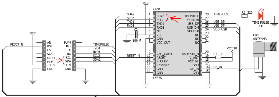 This should make it a whole lot easier to connect an EEPROM to the Click board; it should be possible to tap into the traces adjacent the header pins, as opposed to soldering directly to the castellated pads of the LEA-6S module.
Can we use any generic EEPROM? The Hardware Integration Manual (pdf) says no. Only a handful of EEPROM chips are featured in the table of supported chips on page 13:
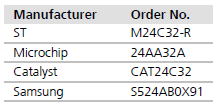 I picked the Microchip 24AA32A because it comes in a hand-solder-able SOT23-5 package, and it’s readily available from RS components (823-0701).
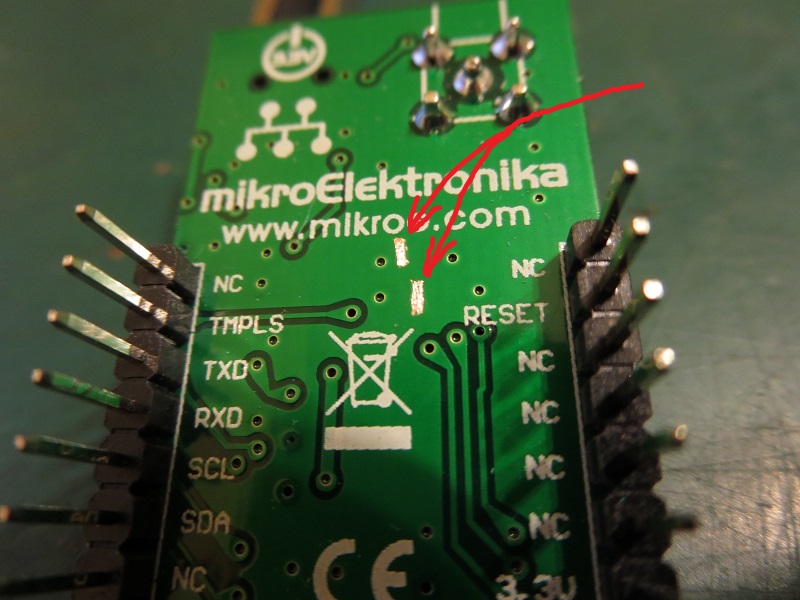
When the chip arrived, I set to work mounting it onto the Click board. I used the chip as a guide to scrape away the solder mask on the underside of the board for two ground connections. The top left connection is needed to pull the write protect pin of the EEPROM to ground, which enables read and write operations to be performed.
 After soldering it to the board, I used magnet wire to connect the remainder of the pins to the adjacent vias for 3.3 volt power, and the SDA and SCL data lines.
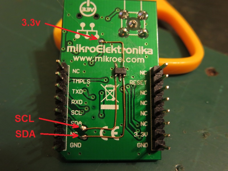
And it’s complete! Now we need to check that configuration settings are actually stored in the EEPROM and retained during a power loss event.
To do this, we use “u-center”, which is a software suite developed by Ublox that can interface with the various GPS modules that they manufacture. I’m using Version 8.23, which can be found on the u-center web site.
When the GPS Click board is connected to the computer with a USB cable, it should enumerate as a virtual COM port.
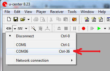
In the top left of the u-center program, use the drop down menu adjacent the “connect” button to establish a serial connection over the associated COM port for the module. This shows up as “COM36” on my machine but may show as a different number:
 Once connected, the output of the module can be checked by opening the text console by selecting “Text Console” under the “View” menu, or by pressing F8:
 The Text Console will open in a separate window that can be placed to the side to monitor the output as we make various configuration changes. The console shows the module is outputting GSV, RMC, GSA, GGA, GLL and VTG NMEA messages. It will always default to this state when the power is lost or the module is reset.

It should be noted that my primary motivations are to change the module UART rate to 115200 baud, and to limit the types of NMEA messages that are sent out from the module. The factory default UART rate is 9600 baud, and the factory default NMEA messages that are sent from the module are: GSV, RMC, GSA, GGA, GLL, VTG, and TXT.
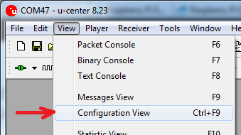
The configuration options can be accessed by selecting “Configuration View” under the “View” menu, or by pressing CTRL+F9:
 The Configuration window will open, showing dozens of different settings grouped into different categories in the left hand side of the window pane.
Modifying Output of NEMA messages
To modify the types of NMEA messages that are sent from the module, find and select “MSG (messages)” in the left hand side of the window pane:
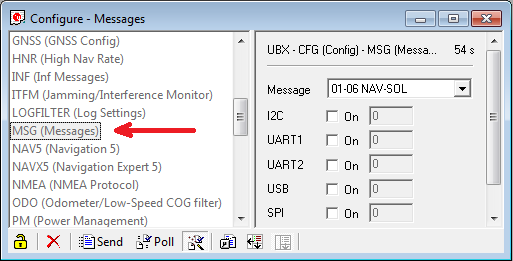
The right hand side should update to show a dropdown list of all possible messages (even non-NMEA ones!), and a series of tick boxes adjacent to the different module communication options.
To check the output options for the “GGA” NMEA sequence, we scroll almost to the bottom of the drop down list, and select “F0-00 NMEA GxGGA”:
 Once selected, the array of tick boxes below the drop down menu will update. Each tick box enables the corresponding module output. The same message can be directed to multiple different outputs:
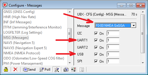
In this case, we see selections to output the sequence over I2C, UART1, UART2, USB, and SPI. This tells us that the GGA message will be sent out over all communication channels.
The “UART1” option controls the hardware UART in/out of the LEA-6S module. The associated pins have been broken out to the Click header.
The “USB” option controls the sending of messages over the virtual COM port established to the computer.
I’ve never actually tried the “I2C” option but I presume that the LEA-6S module can be configured to act as a slave and distribute data over the I2C bus.
The “UART2” and “SPI” options will silently fail as they are not supported by the LEA-6S module.
To change the output options for the “VTG” NMEA sequence, we scroll and select “F0-05 NMEA GxVTG”:
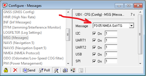
Much like the GGA sequence, every communication option is selected, meaning that the VTG sequence will be sent out over every available communication channel.
In this case we want to eliminate the VTG sequence from being sent out over UART1 and USB, so we deliberately un-tick those options:
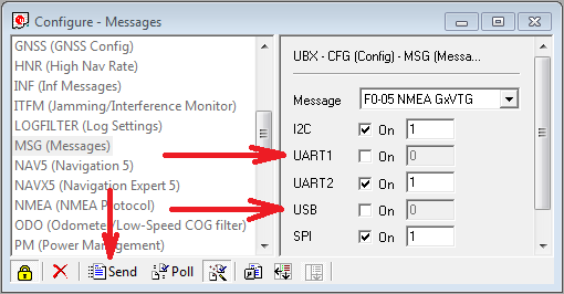
To push these settings to the module, click the “send” button in the bottom left corner of the window. The change should be immediately noticed in the Text Console; the VTG message should no longer appear.
We repeat this exercise for as many different messages as we wish to add or remove, by finding them in the drop down list and changing the tick-boxes adjacent the output options.
I have limited the NMEA messages to only GGA (output over UART1 and USB) and RMC (output over UART1).
Note: some tools within u-center rely on certain NMEA sequences being received over USB e.g. live satellite information can only be displayed if the GSV sequence output is enabled over USB.
Modifying UART baud rate
To change the UART baud rate, find and select “PRT (Ports)” in the left hand side of the window pane. The right hand side of the window will update, showing the various parameters that can be changed.
The dropdown list on the lower right is used to select the desired baud rate which for me is 115200. Clicking the “Send” button in the lower left will instantly update the module:

Storing settings to EEPROM
To permanently store these configuration settings in the newly attached EEPROM chip, find and select “CFG (Configuration)” in the left hand side of the window pane:
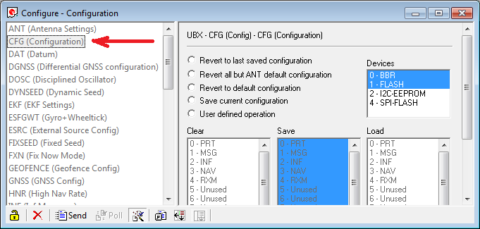
The right hand of the window should update to show various options.
Select the radio button adjacent to “Save current configuration”, and select “2 – I2C-EEPROM” from the “Devices” list on the right hand side. As the final step, click the “send” button in the bottom left of the configuration window:
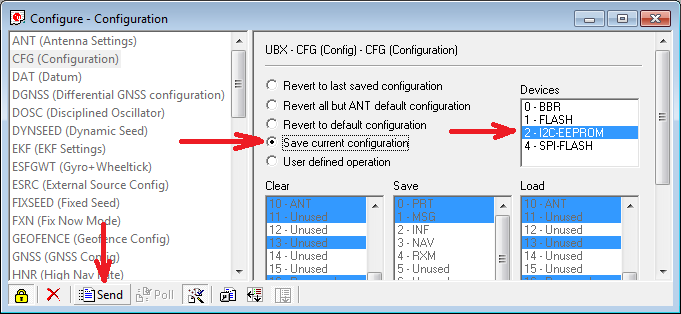
The settings should now be stored in the attached EEPROM chip.
Using a separate UART to USB converter connected to the TX and RX pins of the Click board header, it can be seen that the baud rate has been changed to 115200 baud, and the NMEA messages have been changed to just the GGA and RMC sequences:

And for the final test, the power is removed and re-applied. As hoped, the module retains the baud rate and message settings that have been applied.
And as a final suggestion to MikroElektronika; maybe the next GPS Click board revision could feature a footprint for the EEPROM?
Excellent article!
I am using another kind of breakout board with the Neo-6 and a 24lc32 eeprom, but I cannot get modifications stored in the eeprom in spite of having followed the procedure described.
Modifications are retained is stored in BBR but as long as power is restored before Backup Voltage drops below a certain minimum.